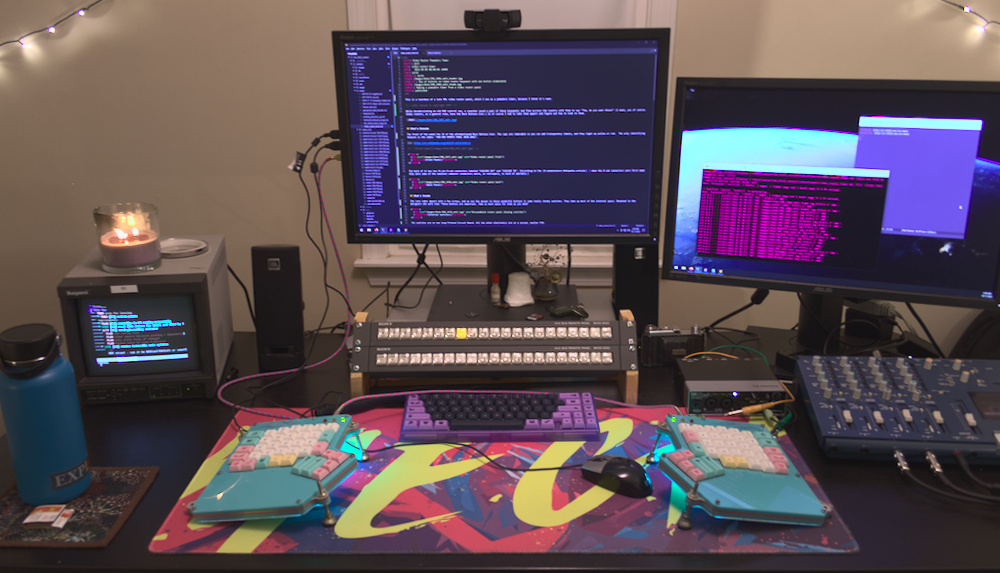
This is a teardown of a late 90s video router panel, which I use as a pomodoro timer. Because I think it's neat.
While decommissioning an old ROV control van, a coworker saved a pair of these keypanels, and flew across the country with them to say "Tim, do you want these?" (I mean, yes of course. Video routers, as a general rule, have the Best Buttons Ever.) That, of course, left me with no choice but to take them appart and see if I could talk to them.
What's Outside
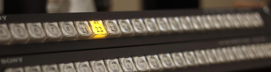
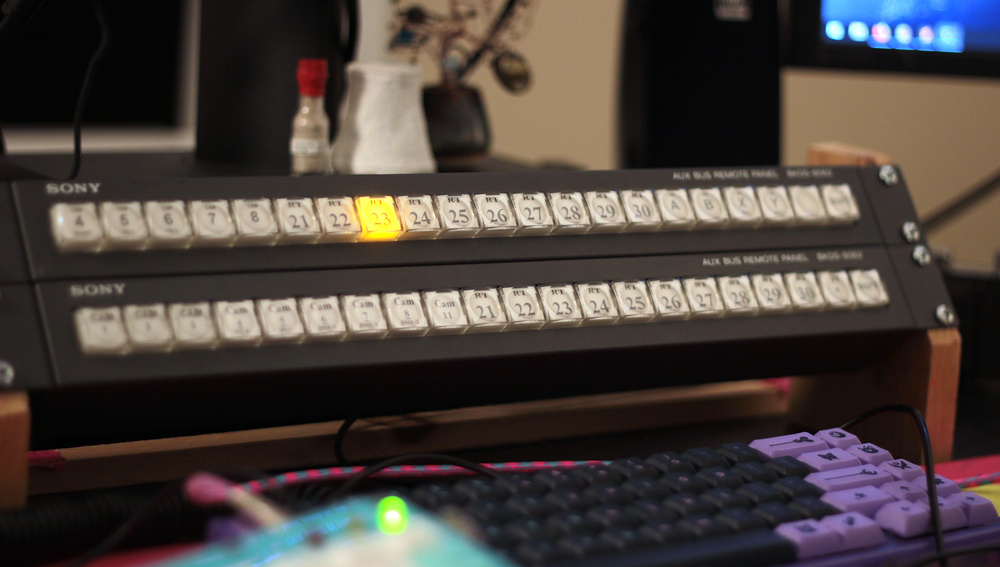
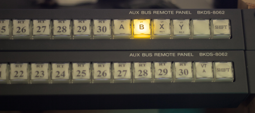
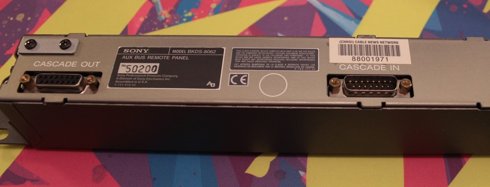
The front of the panel has 21 of the aforementioned Best Buttons Ever. The caps are removable so you can add transparency labels, and they light up yellow or red. The only identifying feature is the label: "AUX BUS REMOTE PANEL BKDS-8062".
The back of it has two 15 pin D-sub connectors labeled "CASCADE OUT" and "CASCADE IN". (According to the D-subminiature Wikipedia article when the D-sub connectors were first made they were some of the smallest computer connectors which, in retrospect, is kind of adorable.)
What's Inside
The case comes apart with a few screws, and we see the answer to those wonderful buttons is some really chonky switches. They take up most of the internal space. Shoutout to the designers who were like "These buttons are important. Take as much space for them as you need"
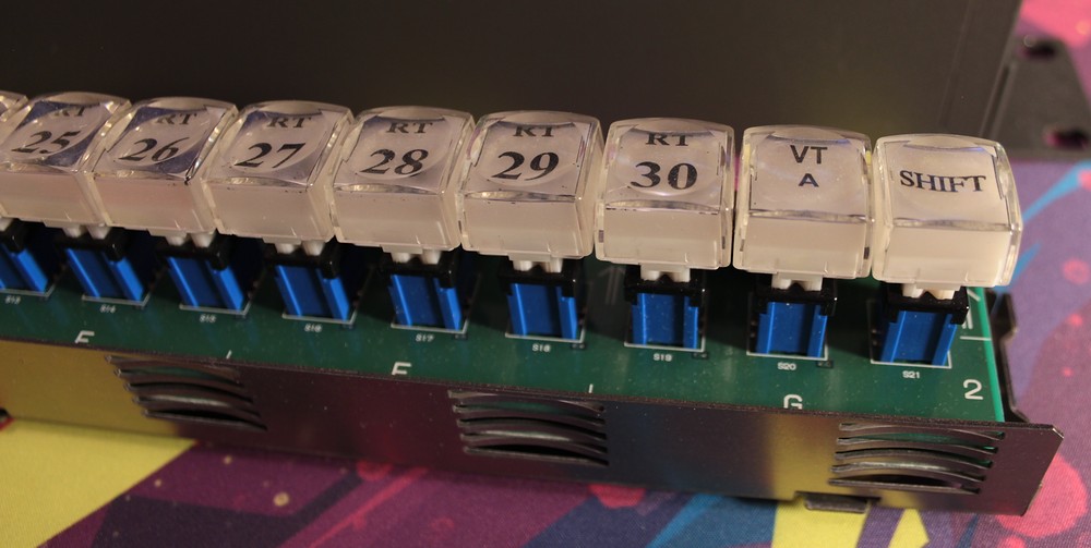
The switches are on one long Printed Circuit Board. All the other electronics are on a second, smaller PCB.
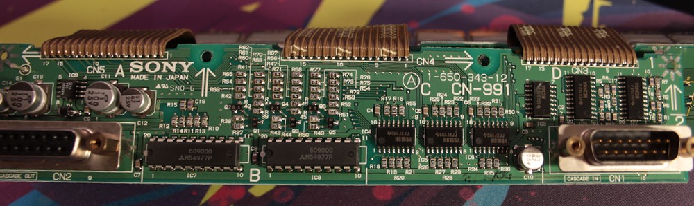
The electronics PCB has a whole bunch of resistors, a few capacitors, and a handful of ICS. Which is to say, it looks like every PCB ever.
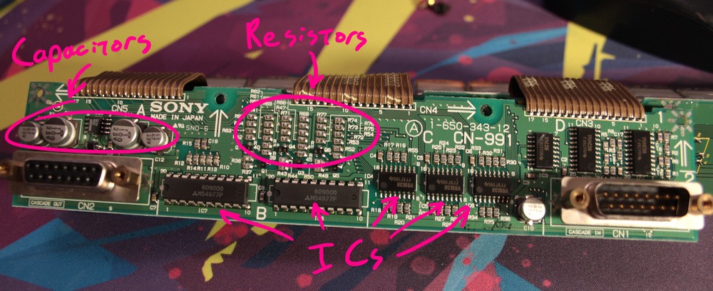
Resistors are boring and just there to make the math work out. We'll ignore those. Capacitors are usually something to do with power management, but also don't tell us much. The good stuff is in the Integrated Circuits, so it's time to start looking up model numbers.
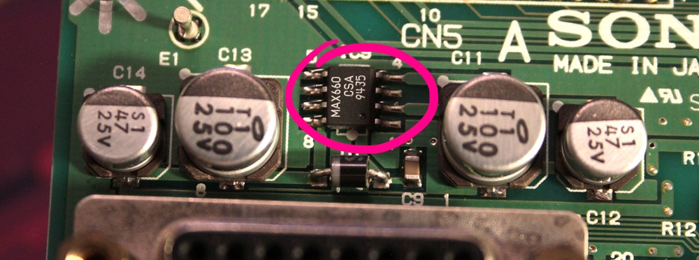
The little one next to the capacitors is a MAX660CSA+ Charge Pump Switching Regulator which sounds like some sort of voltage converter. That section is probably all power management. Good to know. We'll just assume the power is managed and move on.
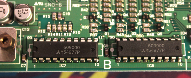
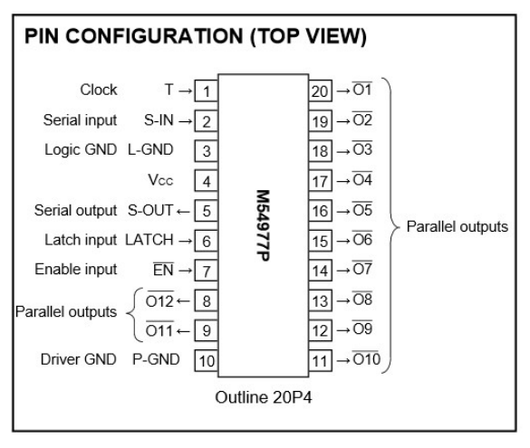
Moving to the right we have these two large ones which appear to be M54977P Serial-Input Latched Drivers. They receive a serial sequence of on and off signals, along with a clock pulse, and turn the output pins on and off accordingly.
The pinout also shows a Latch Input. That prevents the output pins from changing while you're sending it data. A Serial Out lets you daisy chain multiple identical chips together.
These Serial-Input Latched Drivers are used to drive all the LEDs in the buttons. The two chips give 24 total outputs, for the 21 buttons with orange and red LEDs in each of them. They were clever/lazy about changing the colors. The first 21 pins just turn the LEDs on and off. The last three change the colors for either the first button, the last button, or all the buttons in the middle at once. I think this means, under normal use, only one button would be lit at a time - except for the end buttons which can act as shift keys to change the others between multiple banks.
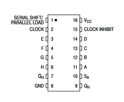
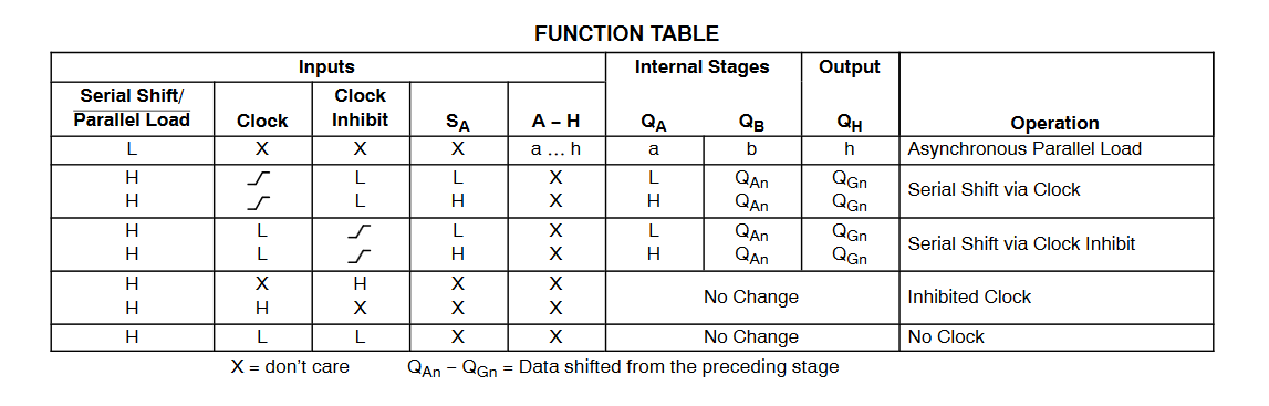
Further to the right, we have these three smaller chips, which appear to be HC165A Parallel-Input/Serial-Output Shift Registers
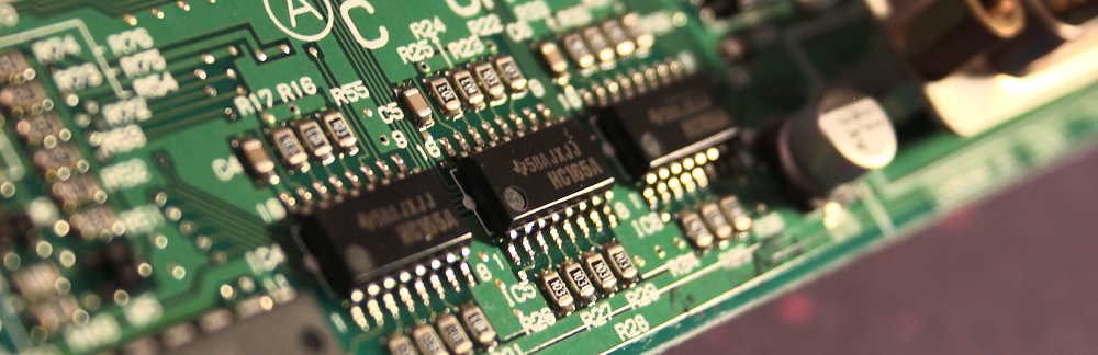
The data sheet pinout and associated function table show this chip works pretty much as the reverse of the above serial-to-parallel IC. It reads the on/off state of eight input pins, and outputs their state in serial sequence when it receives clock pulses. It also has a serial input, so you can daisy chain multiple chips together. With 24 input pins between the three chips, it has enough to read whether any of the 21 buttons are pressed, with a few pins left over.
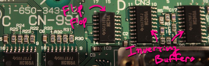
The rest of the ICs aren't all that interesting. There's an HC74A Dual D-Type Flip-Flop which saves the state of the input pin every time it gets a clock signal. There's a pair of HC240A Octal 3-State Inverting Buffer/Line Driver/Line Receivers which is a lot of words to say it inverts the input pins and gives the opposite state to the output pins. Like resistors, these are mostly just there to make the math work out.
I've been ignoring the manual to the router itself thus far, but it's actually kind of great. It gives the following pinout for the BKDS-8062 router panel. Shoutouts to good tech docs.
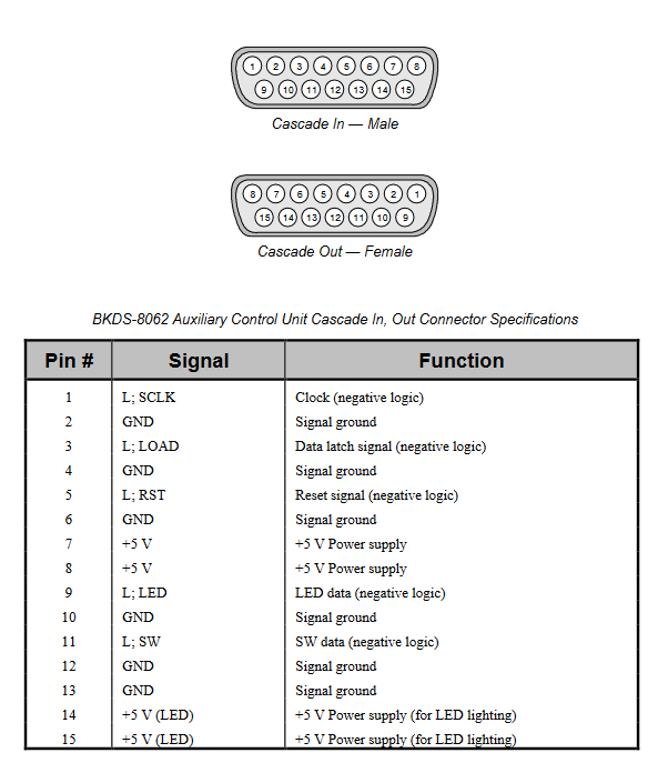
10 of the 15 pins are either power or ground. The remaining pins pretty much match up with the pins that appear on the shift register ICs. We have a clock, LED data, switch data, reset, and data latch. One might assume these are just direct wires to the IC pins. From experimentation I can confirm that is, in fact, what's happening. This thing is remarkably straightforward. I love it.
Talking to the BKDS
Talking to the router panels is pretty straightforward, with the assorted data sheets to help. All you need to do is set the latch pin update mode, then back to data-transfer mode. Then send clock pulses, and with each pulse read a switch state from the switch data pin, and send an LED status to the LED data pin. I wrote some Python code that uses the GPIO pins of a Raspberry Pi to send the correct signals.
The initial code was just a proof of concept, turning on lights or reading buttons. It stayed like that for a while, until the pandemic reached North America. Working from home I realized I needed any possible tool to help track the passage of time, so I added some code to use the lights in the buttons as a visual pomodoro timer.
So that's how a piece of a 20+ year old video router became an important part of my workflow.
Note: If you enjoy reverse engineering old TV production equipment (and who doesn't?) I highly recommend Glen Akins blog. He's taken it much further than I have, and it's honestly wonderful.